Search
Abstract
Abstract:Based on the analysis of the requirements of OEB5 grade pharmaceutical factory on the production environment, the design essentials of HVAC division, differential pressure control, ozone disinfection setting, aseptic isolator exhaust and room exhaust requirements in HVAC design of a highly toxic drug workshop in a hot summer and cold winter area in China were summarized.
Keywords:high active;OEB5 grade;HVAC design;sterile isolator; clean air conditioning
1. Introduction to OEB5
Occupational Exposure Limit (OEL) is the maximum airborne particle concentration of a certain pollutant at which exposing workers to it repeatedly and for a long duration during occupational activities would not cause harm to the health of the majority of exposed workers. It quantitatively determines the hazardous nature of the substance.
Occupational Exposure Band (OEB) is used to classify pharmaceutical compounds into different hazard classes instead of specifying a numerical limit. It qualitatively determines the hazardous nature of the substance based on the following factors:
1、Activity
2、Pharmacological effects
3、 Side effects/toxicological effects
4、 Inclusion of the OEL value within these categories
(For example, for classes 1 to 4 or 5, their activities increase from low to high)
OEB5 typically corresponds to an OEL range less than 1 μg/m3 and the compounds at this level are with extremely toxic or high pharmacological activity.
For product lines involving API of OEB5, fully enclosed equipment shall be used. Control measures such as negative pressure isolator, closed operations in glove box, closed transfer interfaces (such as split butterfly valve), bag-in/bag-out filtration devices and independent air purification system shall be taken. Strict controls shall be maintained over personnel and material flow, entrance, airlocks, pressure gradients in rooms, and maintenance and cleaning of the workshop.
2. Design Overview
2.1 Project Overview
The building is located in a region hot in summer and cold in winter. It is classified as a Class C pharmaceutical engineering design with a fire resistance rating of 2. In it, two production lines are designed, which are the microsphere preparation line and the microsphere filling line.
2.2 Environmental Control Requirements for Production Processes
The main production processes shall be finished inside the sterile isolators and negative pressure isolators. The isolator operation techniques shall be used to protect the core operating area. The air entering the isolators shall be filtered with bag-in/bag-out filters. Operators shall be completely isolated from the core processes, and their interventions in the core processes shall be done through gloves and glove sleeves. Materials and equipment entering and exiting the isolator must be sterilized and transferred with sterile transfer devices [1].
The required temperature and humidity for the process shall be maintained by the isolator HVAC system. The active isolators with their own air treatment systems shall be used, providing good environmental isolation, and their requirements for the HVAC systems in the production area are relatively low. The cleanliness inside the isolator shall be set at Grade A, while the background environmental cleanliness for both production lines shall be set at Grade C. The requirements for the background environmental temperature and humidity shall set according to the specifications, which are as follows: temperature 20-24°C and relative humidity 45-60%.
3. HVAC System Zoning
On one hand, the risk levels of rooms shall be determined according to the room types. For high-risk rooms, low-risk rooms, and risk-free rooms, separate air conditioning zones can be established [2].
Risk-free rooms are the ones where no highly active, highly toxic, or highly allergenic substances are used or stored. These rooms are generally smaller in size, and certain rooms, such as shoe-changing and dressing rooms, require complete air exhaust. If a separate HVAC system is established for risk-free areas, it would increase the construction cost due to additional air conditioning equipment, ductwork, accessories, bag-in/bag-out filters, etc. The energy-saving effect achieved by utilizing the return air from it may not be significant. Moreover, in the event of a sudden pressure loss in a room, the toxic substances could potentially permeate into risk-free rooms, posing potential hazards to the personnel.
On the other hand, a production schedule shall be planned according to the production capacity required, and separate HVAC zones can be divided for different scheduling times to facilitate production adjustments.
In summary, it is considered appropriate to establish HVAC zones separately for the two lines.
4. Differential Pressure Control Strategy
4.1 Differential Pressure Control Requirements
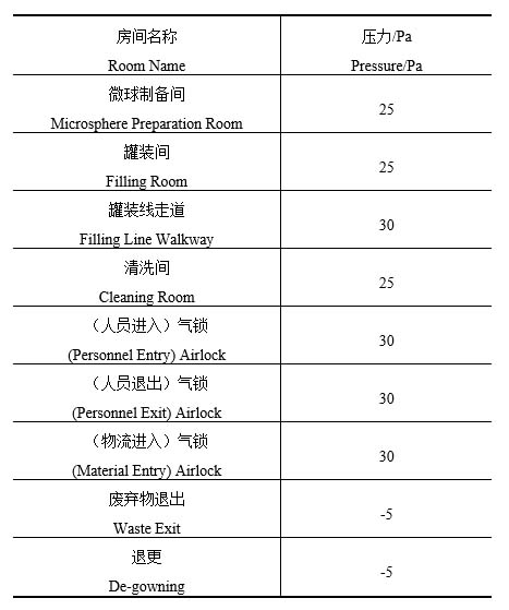
1、The core area shall be identified. As the product leakage in the core area would have an impact on the surrounding environment, it shall be maintained at a relative negative pressure compared to surrounding rooms;
2、Rooms that produce more dust or steam, such as material cleaning rooms or garment washing rooms, shall be maintained at a relative negative pressure compared to surrounding rooms;
3、 For exit pathways of personnel and waste exit rooms that involve the risk of exposure or leakage of highly active substances, such as de-gowning room and waste exit room, they shall be maintained at a relative negative pressure compared to the outdoor atmosphere;
4、The airlocks for personnel and material entry are free of highly active substances, so the positive pressure airlocks shall be installed to prevent outdoor dust and microorganisms from entering the clean room. The airlocks for personnel exit pathways shall also be maintained at positive pressure because the de-gowning room is maintained at a relative negative pressure compared to the outdoor atmosphere;
5、If the cleanliness of the rooms on both sides of the airlock is different, the differential pressure between the rooms on the two sides of the airlock shall be 10 Pa. The differential pressure between the clean room and the airlock is not required to be 10 Pa [1].
Based on the above control requirements, the differential pressures for typical rooms are shown in Table 1:
4.2 Differential Pressure Control Means
The fans and exhaust fans of air conditioning units shall be equipped with variable frequency drives (VFD). The VFDs will adjust the motor speeds of the fans according to the static pressure sensors on the supply and exhaust ducts.
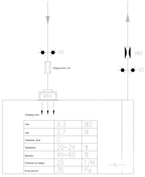
At the air supply ends in the rooms, constant air volume (CAV) valves are installed to ensure a consistent supply airflow. Variable air volume (VAV) valves can be used at the air exhaust ends to regulate the differential pressure indoor, creating a stable differential pressure airflow, so as to control a stable differential pressure in the room. The CAV valves are equipped with dual-position controls for two airflow settings: one for normal operation and the other for disinfection mode. Under disinfection mode, the negative or positive pressure state in the room shall be maintained.
In addition, manual control valves shall be installed on the branch lines of the CAV and VAV valves, which can be manually adjusted to assist in pressure regulation when the pressure exceeds the design range.
A zero-pressure loop is set up in the technical interlayer, and the pressure control of each room shall be connected to this loop to ensure that the reference pressures of all rooms covered by this functional unit are the same.
The differential pressure control diagram of the room can be seen in Figure 1.
5. HVAC System
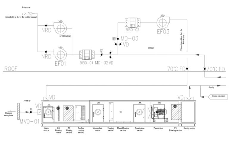
Highly active and highly toxic APIs pose great harm to personnel. The exhaust from the rooms must be completely discharged without returning to the HVAC system. Therefore, a straight-flow full fresh air system shall be used for the HVAC.
As it is a full fresh air system without any return air ducts, a separate air circulation branch is required for disinfection mode. The design concept involves connecting a branch to the main exhaust duct, and installing a bag-in/bag-out high-efficiency filter and a circulation fan following the branch. The circulation fan shall only operates under disinfection mode and remain off during normal operation.
Please refer to Figure 2 for the flowchart of the straight-flow full fresh air system:
6. Filtration Strategy
The supply air system is designed with a three-stage filtration process, including primary, intermediate, and high-efficiency filters.
The bag-in/bag-out high-efficiency filters shall be installed at the inlet and exhaust ports of the sterile isolator.
Considering that the processes of core production area occur inside the isolator, the exhaust system shall incorporate filter screens at the exhaust ports, and bag-in/bag-out filters in the negative pressure section of the exhaust duct. The filters at exhaust ports shall be the bag-in/bag-out filters, depending on the specific process requirements. Prior to filter replacement, disinfection is necessary to prevent contamination of the air by toxic and hazardous substances and to ensure the safety of the operator.
The bag-in/bag-out high-efficiency filters shall be deployed in a two-stage design. If the first-stage filter leaks, the second-stage filter would act as a backup, providing dual protection to ensure the safety of discharged air and reducing the risk of environmental contamination caused by filter leakage [3]. However, the use of two-stage filters increases the pressure head of the fan. Whether to use the two-stage filters shall be evaluated based on process requirements. The bag-in/bag-out filters shall be equipped with disinfection inlets and outlets, such as ball valves or butterfly valves, as well as quick-connect disinfection couplings for external connections. Both ends of the bag-in/bag-out filters shall be installed with operable biological airtight valves to ensure the airtightness throughout the chamber during disinfection [4].
7. Exhaust Strategy
7.1 Equipment Exhaust
The design of equipment exhaust shall be designed based on the exhaust volume and form provided by the manufacturer. The equipment exhaust system shall not be combined with the room exhaust system, and the supply and exhaust systems of each equipment shall be independent.
As the exhaust from equipment exhaust system usually is higher in temperature and may need to be dehumidified, stainless steel ducts are typically used for equipment exhaust system.
7.2 Room Exhaust
For rooms generating high-temperature and high-humidity gases, overhead exhaust shall be employed. Rooms with equipment exhaust also require parallel duct for exhaust to balance the differential pressures within the rooms. For exhaust that is prone to condensation, drain pipes shall be installed.
To enhance the safety and stability of the HVAC system and facilitate the discharge of high-activity and high-toxicity exhaust, one exhaust fan shall be used in the exhaust system with an additional as the backup to discharge the exhaust to a safe location outdoor. Additionally, the effective height of the exhaust ducts shall be sufficient to discharge the exhaust beyond the aerodynamic shadow area and positive pressure zone of the building, meeting the emission height requirements specified in relevant regulations, and ensuring the effective spread of the exhaust to avoid it from returning to the intake or reaching the roof. Under disinfection mode, the exhaust fan shall operate at variable frequency based on the disinfection airflow.
8. Conclusion
In conclusion, for the design of HVAC system in a pharmaceutical plant of OEB5 and producing highly active APIs, the main focus is on the control of core working area within enclosed spaces which is achieved through the equipment such as sterile isolators and negative pressure isolators, as well as controlling the temperature, humidity and relative pressure within the isolators to mitigate the risk of leakage of high-activity substances. It is also important to maintain stable differential pressures in ancillary rooms and the background environment of the isolators and to carefully design the relative pressure values. The exhaust system shall be set up according to process requirements; and the positioning and filtration strategy of high-efficiency filters in the entire system shall be designed properly.
References::
[1] 张爱萍,孙咸泽.药品GMP指南 厂房设施与指南[M].北京:中国医药科技出版社,2011:374-375,383-386
[2] 邱济夫.高活性、高毒性、高致敏性药品生产净化空调设计若干问题的探讨[J].暖通空调,2021,51(4):95-99
[3] 金仁良,张爱健,王明丽等. 袋进袋出设备的设计[J].洁净与空调技术,2021(4):97-101
[4] 金仁良,张爱健,王明丽等. 袋进袋出过滤装置的消毒[J].洁净与空调技术,2022(1):115-119
[5][2022-04-26]. https://ishare.iask.sina.com.cn/f/1N2Aw3lyWaJ.html
About Morimatsu Life Science
Morimatsu Life Science is the sanitary business segment of Morimatsu International Holding Co., Ltd. (Morimatsu International, stock code: 2155.HK), covering industries such as pharmaceuticals, biopharmaceuticals, FMCG, cosmetic and electronic chemicals, and mainly includes Shanghai Morimatsu Pharmaceutical Equipment Engineering Co., Ltd., Morimatsu (Suzhou) Life Technology Co., Ltd., Shanghai Morimatsu Biotechnology Co., Ltd., Shanghai Senzhong Biotechnology Co., Ltd., Pharmadule Morimatsu AB (Sweden) and other companies and their affiliates, focusing on the R&D, manufacturing and sales of products in related fields.
Morimatsu, founded in Japan and taken root in China, has developed into a multi-national company that embraces globalization, masters core technology, and gains rich experience from project implementation in diverse fields including core equipment, process systems, and engineering solutions. Starting from its advanced manufacturing base in China, Morimatsu International has opened subsidiaries or plants in Sweden, the United States, India, Italy, Malaysia and Singapore, and has delivered different forms of products and services to more than 40 countries and regions so far, by virtue of its global footprint of efficient and professional team.
Forward-Looking Statements
The information in this press release may include some forward-looking statements. Such statements are essentially susceptible to considerable risks and uncertainties. The use of “predicted”, “believed”, “forecast”, “planned” and/or other similar words/phrases in all statements related to our company is to indicate that the statements are forward-looking ones. Our Company undertakes no obligation to constantly revise such predicted statements.
Forward-looking statements are based on our Company management’s current perspectives, assumptions, expectations, estimations, predictions and understanding of future affairs at the time of the making of such statements. Such statements are not guaranties of future development and are susceptible to the impact of risks, uncertainties and other factors; some are beyond the control of our Company and unpredictable. Subject to the influence of future changes and development in our business, competition environment, political, economic, legal and social conditions, the actual outcomes may differ significantly from the information contained in the forward-looking statements.